对于XRR的拟合,显然GenX是更为强大和方便的。然而也面临着拟合参数选取过于依赖经验,经常过拟合或者无法拟合的现象。
xrayutilities采用lmfit模块进行拟合。我们首先对官方给出的教程进行学习。然后逐步扩展到其他衬底和材料。
数据的导入
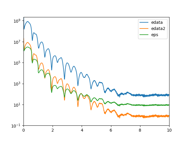
1 2 3 4 5 6 7 8 9 10 11 12 13 14 15 16 17 18 19 20 import osimport lmfitimport matplotlib.pylab as pylabimport matplotlib.pyplot as pltimport numpyimport xrayutilities as xuai, edata, eps = numpy.loadtxt(os.path.join('data' , 'xrr_data.txt' ), unpack=True ) ai /= 2.0 plt.plot(ai, edata) edata2 = edata/1E2 plt.plot(ai,edata2) plt.plot(ai, eps)
上述代码运行结果
从图中可以看出,强度除以200的值和eps还是有差异的。
定义材料与模型创建
1 2 3 4 5 6 7 8 9 10 11 12 13 14 15 lSiO2 = xu.simpack.Layer(xu.materials.SiO2, numpy.inf, roughness=2.5 ) lRu = xu.simpack.Layer(xu.materials.Ru, 47 , roughness=2.8 ) rho_cf = 0.5 *8900 + 0.5 *7874 mat_cf = xu.materials.Amorphous('CoFe' , rho_cf) lCoFe = xu.simpack.Layer(mat_cf, 27 , roughness=4.6 ) lIrMn = xu.simpack.Layer(xu.materials.Ir20Mn80, 21 , roughness=3.0 ) lAl2O3 = xu.simpack.Layer(xu.materials.Al2O3, 100 , roughness=5.5 ) m = xu.simpack.SpecularReflectivityModel(lSiO2, lRu, lCoFe, lIrMn, lAl2O3, energy='CuKa1' , resolution_width=0.02 , sample_width=6 , beam_width=0.25 , background=81 , I0=6.35e9 )
基本没有太多新的知识,只需要根据别的教程建立自己的材料就可以了。至于模型创建中的参数,还需要结合个人具体实验情况。
设定拟合参数
1 2 3 4 5 6 7 8 9 fitm = xu.simpack.FitModel(m, plot=True , verbose=True ) fitm.set_param_hint('SiO2_density' , vary=False ) fitm.set_param_hint('Al2O3_density' , min =0.8 *xu.materials.Al2O3.density, max =1.2 *xu.materials.Al2O3.density) p = fitm.make_params() fitm.set_fit_limits(xmin=0.05 , xmax=8.0 )
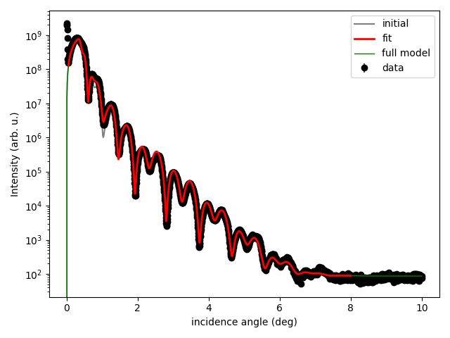
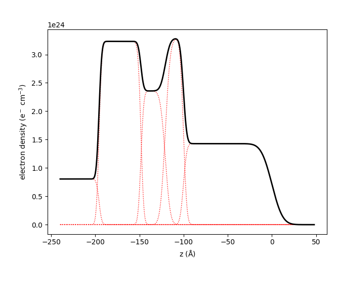
lmfit.Model下的函数,用来设置拟合参数的约束、限制等等。具体参数含义如下: 1 2 3 4 5 6 7 8 9 10 11 12 13 14 15 16 17 18 19 20 21 22 23 * name: 参数名称 * vary: 参数在拟合期间是否变化,默认为True * min、max是模拟的最大最小值,默认无上下限。-numpy.inf,没有下限。numpy.inf,无上限。 ## 拟合并保存拟合结果 ```python # perform the fit res = fitm.fit(edata, p, ai, weights=1/eps) # eps换成edata2也没有影响拟合结果 lmfit.report_fit(res, min_correl=0.5) m.densityprofile(500, plot=True) pylab.show() # export the fit result for the full data range (Note that only data between # xmin and xmax were actually optimized) # 注意只保存了拟合数据,但是拟合参数结果并没有保存 numpy.savetxt( "xrrfit.dat", numpy.vstack((ai, res.eval(res.params, x=ai))).T, header="incidence angle (deg), fitted intensity (arb. u.)", )
实际应用
建立衬底晶体结构
对\(\ce{YNiO3}\) /\(\ce{YAlO3}\) 样品进行拟合,首先是定义材料。
对于\(\ce{YAlO3}\) ,文献中的晶体结构是Pbnm,然而62空间群常规而言是Pnma。需要将原子坐标\((x, y,
z)\) 进行转换。也就是给坐标向量乘如下矩阵:
\[\begin{bmatrix}
0 & 0 & 1\\
1 & 0 & 0\\
0 & 1 & 0
\end{bmatrix}\]
1 2 3 Pbnm空间群的a轴等同于Pnma空间群的c轴; Pbnm空间群的b轴等同于Pnma空间群的a轴; Pbnm空间群的c轴等同于Pnma空间群的b轴。
因此,材料定义如下: 1 2 3 4 5 6 7 YAlO3 = Crystal("YAlO3" , SGLattice(62 , 5.30102 , 7.34181 ,5.16098 , atoms=[e.Y, e.Al, e.O, e.O], pos=[('4c' , (0.05195 , -0.01158 )), '4b' , ('8d' , (0.2933 , 0.0431 , 0.7054 ,) ), ('4c' , ( 0.4805 , 0.0832 ) ) ]))
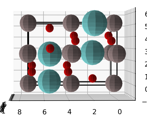
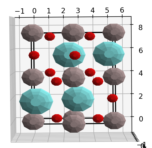
然后,绘制出晶体结构,看构建的晶体是否正确。 1 2 3 4 5 6 7 import matplotlib.pyplot as pltfrom xrayutilities.materials import predefined_materialsYAlO3 = predefined_materials.YAlO3 f = plt.figure() YAlO3.show_unitcell(fig=f, subplot=121 )
建立薄膜晶体结构
除了自己建立晶体结构以外,还可以导入cif文件。
1 YNiO3 = xu.materials.Crystal.fromCIF(os.path.join("/data" , "YNiO3.cif" ))
然而实际中发现导入cif文件后晶体的命名并非预期情况。因此,可能根据cif文件,自己建立晶体结构是最好的选择。
创建模型
参考